


random user submitted photo
DIY-EFI
Re: DIY-EFI
![]() by Bryan Cotton » Sun May 16, 2021 12:22 pm
by Bryan Cotton » Sun May 16, 2021 12:22 pm
phenry wrote:My EFI system is moving from experiment to refined/final version.
Peter Henry
Waiex #149
Very cool!
Bryan Cotton
Poplar Grove, IL C77
Waiex 191 N191YX
Taildragger, Aerovee, acro ailerons
dual sticks with sport trainer controls
Prebuilt spars and machined angle kit
Year 2 flying and approaching 200 hours December 23
Poplar Grove, IL C77
Waiex 191 N191YX
Taildragger, Aerovee, acro ailerons
dual sticks with sport trainer controls
Prebuilt spars and machined angle kit
Year 2 flying and approaching 200 hours December 23
-

Bryan Cotton - Posts: 5073
- Joined: Mon Jul 01, 2013 9:54 pm
- Location: C77
Re: DIY-EFI
![]() by WesRagle » Tue May 25, 2021 6:49 pm
by WesRagle » Tue May 25, 2021 6:49 pm
Hi Guys,
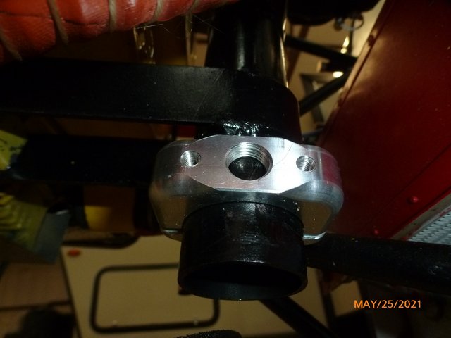
My ECU project is moving along. I don't want to find myself all dressed up with no place to go. So ... I'm looking for ways to implement the physical side of data acquisition. At present I believe the only external analog signals I want to acquire are Battery Voltage, Inlet Air Temperature, Manifold Pressure, and Engine Temp. Since I don't weld I've been looking for a "cheat" on MAP and IAT. While poking around on the web I found this:
https://www.speedwaymotors.com/All-In-One-Roll-Bar-Accessory-Clamps,42491.html.
I bought the 1.5" version and sure enough, it appears to be a near perfect fit.
While looking for sensors, I came across this:
https://www.ebay.com/itm/264607384540
Dimensional Drawing is near the bottom of the page.
It looks like with an adapter plate, proper reaming, and some RTV to ensure a good seal against the intake pipe I'll have a workable solution for MAP and IAT without welding.
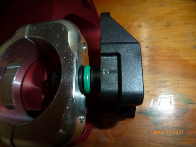
Question for those with machinist experience: The business end of the MAP/IAT sensor is shown to be 12 mm. Is that the size reamer I should order? Am I to assume that the O-ring will compress in the groove to match the 12 mm OD?
Thanks,
Wes
My ECU project is moving along. I don't want to find myself all dressed up with no place to go. So ... I'm looking for ways to implement the physical side of data acquisition. At present I believe the only external analog signals I want to acquire are Battery Voltage, Inlet Air Temperature, Manifold Pressure, and Engine Temp. Since I don't weld I've been looking for a "cheat" on MAP and IAT. While poking around on the web I found this:
https://www.speedwaymotors.com/All-In-One-Roll-Bar-Accessory-Clamps,42491.html.
I bought the 1.5" version and sure enough, it appears to be a near perfect fit.
While looking for sensors, I came across this:
https://www.ebay.com/itm/264607384540
Dimensional Drawing is near the bottom of the page.
It looks like with an adapter plate, proper reaming, and some RTV to ensure a good seal against the intake pipe I'll have a workable solution for MAP and IAT without welding.
Question for those with machinist experience: The business end of the MAP/IAT sensor is shown to be 12 mm. Is that the size reamer I should order? Am I to assume that the O-ring will compress in the groove to match the 12 mm OD?
Thanks,
Wes
Wes Ragle
Onex #89
Conventional Gear
Long Tips
Hummel 2400 w/Zenith Carb
Prince P Tip 54x50
First Flight 06/23/2020
42.8 Hrs. as of 10/30/21
Onex #89
Conventional Gear
Long Tips
Hummel 2400 w/Zenith Carb
Prince P Tip 54x50
First Flight 06/23/2020
42.8 Hrs. as of 10/30/21
- WesRagle
- Posts: 846
- Joined: Fri Jan 05, 2018 12:35 pm
- Location: Weatherford, Tx
Re: DIY-EFI
![]() by thomas » Wed May 26, 2021 8:21 pm
by thomas » Wed May 26, 2021 8:21 pm
Hi Wes,
I so much enjoy your posts - thank you for the detailed explanations you are sharing.
For sizing o-ring hole diameters, I measure the actual outside diameter of the cylinder that carries the o-ring (the MAP/IAT sensor business end) and add 0.001” to the ID I want to ream. Almost never do I have a reamer that is exactly the size I need. In practicality, I’d find a reamer about 0.001” to 0.010” over the cylinder OD for a hole slightly over 1/2”. If the gap is too large, the o-ring may pinch between the OD and ID during assembly. Hopefully, your sensor cylinder OD is slightly under 12mm and you can buy a basic 12mm reamer. A good chamfer on the hole entrance and very light coating of o-ring compatible lube will make up for any o-ring tightness on assembly.
I look forward to reading more posts from you as you pioneer this system.
Best,
Paul
- thomas
- Posts: 59
- Joined: Sat Aug 27, 2016 9:45 am
Re: DIY-EFI
![]() by WesRagle » Thu May 27, 2021 10:47 am
by WesRagle » Thu May 27, 2021 10:47 am
HI Paul,
Thanks for the reply, and the kind words.
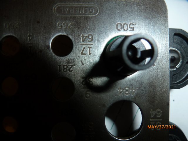
I pulled out my somewhat flaky calipers and the shaft of the probe measures 0.467 (11.86 mm). Since 12 mm = 0.472, it looks like if I order a 12 mm reamer it will put me right in the center of the range you suggest (0.005 Oversize). Sound about right?
It turns out that the threaded hole in the center of the clamp is for a 1/2" bolt. So, the reamer isn't going to remove all of the threads. I may have to apply some silicon sealer to seal around the O-ring depending on the penetration I want.
We'll See,
Wes
Thanks for the reply, and the kind words.
I pulled out my somewhat flaky calipers and the shaft of the probe measures 0.467 (11.86 mm). Since 12 mm = 0.472, it looks like if I order a 12 mm reamer it will put me right in the center of the range you suggest (0.005 Oversize). Sound about right?
It turns out that the threaded hole in the center of the clamp is for a 1/2" bolt. So, the reamer isn't going to remove all of the threads. I may have to apply some silicon sealer to seal around the O-ring depending on the penetration I want.
We'll See,
Wes
Wes Ragle
Onex #89
Conventional Gear
Long Tips
Hummel 2400 w/Zenith Carb
Prince P Tip 54x50
First Flight 06/23/2020
42.8 Hrs. as of 10/30/21
Onex #89
Conventional Gear
Long Tips
Hummel 2400 w/Zenith Carb
Prince P Tip 54x50
First Flight 06/23/2020
42.8 Hrs. as of 10/30/21
- WesRagle
- Posts: 846
- Joined: Fri Jan 05, 2018 12:35 pm
- Location: Weatherford, Tx
Re: DIY-EFI
![]() by thomas » Thu May 27, 2021 2:24 pm
by thomas » Thu May 27, 2021 2:24 pm
Hi Wes,
The RTV may work in the beginning but could really frustrate you over time if small air leaks develop between the sharp edges of the partially-drilled thread grooves and the OD of the o-ring.
My suggestion would be to chamfer and ream a 1/2" hole in a piece of scrap aluminum and test fit the o-ring assembly. It looks like your sensor has a reasonably fat o-ring. So, depending on the depth they set the o-ring groove, there may still be ample o-ring squish to seal inside the .500" hole. As long as you are able to feel reasonable friction as the o-ring slides into the hole, you should be ok. The excessive gap (.500 - .467)/2 = .017" should still be fine because you are sealing such a low pressure differential (14.7 psi at full vacuum).
PM me your address if you need a 1/2" reamer mailed. I live in Houston and could send it out today.
Paul
- thomas
- Posts: 59
- Joined: Sat Aug 27, 2016 9:45 am
Re: DIY-EFI
![]() by WesRagle » Thu May 27, 2021 3:45 pm
by WesRagle » Thu May 27, 2021 3:45 pm
HI Paul,
Thanks, looks like 1/2" will work.
Wes
Thanks, looks like 1/2" will work.
Wes
Wes Ragle
Onex #89
Conventional Gear
Long Tips
Hummel 2400 w/Zenith Carb
Prince P Tip 54x50
First Flight 06/23/2020
42.8 Hrs. as of 10/30/21
Onex #89
Conventional Gear
Long Tips
Hummel 2400 w/Zenith Carb
Prince P Tip 54x50
First Flight 06/23/2020
42.8 Hrs. as of 10/30/21
- WesRagle
- Posts: 846
- Joined: Fri Jan 05, 2018 12:35 pm
- Location: Weatherford, Tx
Re: DIY-EFI
![]() by phenry » Wed Jun 16, 2021 9:59 pm
by phenry » Wed Jun 16, 2021 9:59 pm
I finally got out to the hangar to install the new intakes for my Aerovee / EFI, here are a couple of pictures. Ran really well.
- Intake3.jpg (76.35 KiB) Viewed 3801 times
- Intake2.jpg (38.15 KiB) Viewed 3801 times
Last edited by phenry on Thu Jun 17, 2021 7:33 pm, edited 1 time in total.
Peter Henry
W#149
W#149
-

phenry - Posts: 59
- Joined: Tue Nov 22, 2011 11:29 pm
- Location: Newborough Vic. Australia
Re: DIY-EFI
![]() by WesRagle » Thu Jun 17, 2021 5:22 pm
by WesRagle » Thu Jun 17, 2021 5:22 pm
Hey Peter,
That looks great! However, I see trouble in my Onex future.
Wes
That looks great! However, I see trouble in my Onex future.
Wes
Wes Ragle
Onex #89
Conventional Gear
Long Tips
Hummel 2400 w/Zenith Carb
Prince P Tip 54x50
First Flight 06/23/2020
42.8 Hrs. as of 10/30/21
Onex #89
Conventional Gear
Long Tips
Hummel 2400 w/Zenith Carb
Prince P Tip 54x50
First Flight 06/23/2020
42.8 Hrs. as of 10/30/21
- WesRagle
- Posts: 846
- Joined: Fri Jan 05, 2018 12:35 pm
- Location: Weatherford, Tx
Re: DIY-EFI
![]() by phenry » Thu Jun 17, 2021 7:32 pm
by phenry » Thu Jun 17, 2021 7:32 pm
Yes Wes,
That extra engineering is going to look a bit odd hanging out the side of a Onex.
That extra engineering is going to look a bit odd hanging out the side of a Onex.
Peter Henry
W#149
W#149
-
phenry - Posts: 59
- Joined: Tue Nov 22, 2011 11:29 pm
- Location: Newborough Vic. Australia
Re: DIY-EFI
![]() by phenry » Sat Jun 19, 2021 11:01 pm
by phenry » Sat Jun 19, 2021 11:01 pm
Here is the final piece of the puzzle, crank position sensor.
I used a Honeywell 1GT101DC gear-tooth sensor because I had one laying around, there are probably better sensors around and it does require a pull up resistor to work properly with the Microsquirt ECU. Having said that it works perfectly.
I use extended propeller bolts to trigger the sensor, one bolt is shorter than the other five and this bolt provides the "missing pulse" that starts the injection sequence.
Refining the bracket that holds the sensor will probably next receive my attention, however it works just fine. I had considered a much more complicated arrangement with a notched wheel on the prop shaft or on the rear ignition triggers but it does not fit with my "keep it simple approach.
Some may comment about out of balance forces with different length bolts I am at the moment prepared to live with tiny effect if any. The bolts could probably be shortened with the sensor set closer to the hub and still work, I just haven't bothered.
- CrankPos1.jpg (77 KiB) Viewed 3560 times
- CrankPos2.jpg (64.6 KiB) Viewed 3560 times
- CrankPos3.jpg (53.29 KiB) Viewed 3560 times
Peter Henry
W#149
W#149
-
phenry - Posts: 59
- Joined: Tue Nov 22, 2011 11:29 pm
- Location: Newborough Vic. Australia
Who is online
Users browsing this forum: No registered users and 4 guests