


random user submitted photo
The VeeCU
Re: The VeeCU
![]() by WesRagle » Wed Aug 18, 2021 3:45 pm
by WesRagle » Wed Aug 18, 2021 3:45 pm
Hi Guys,
I pulled a single phase of the alternator over to the bench. This is what I saw.
Alternator without regulator (Raw alternator):
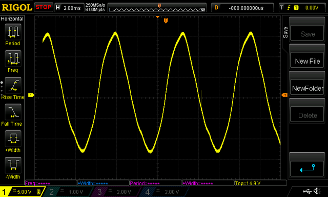
1) Alternator through a 4.7K and a 3V zener.
2) Alternator with regulator in the circuit.
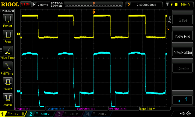
1) Alternator through an opto-isolator with output pulled to 5 volts.
2) Alternator with regulator in the circuit.
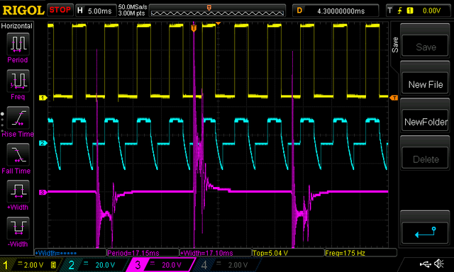
3) P-Lead showing six alternator pulses per revolution.
I think I'll go with the isolated solution to keep the digital ground as isolated as possible.
Wes
I pulled a single phase of the alternator over to the bench. This is what I saw.
Alternator without regulator (Raw alternator):
1) Alternator through a 4.7K and a 3V zener.
2) Alternator with regulator in the circuit.
1) Alternator through an opto-isolator with output pulled to 5 volts.
2) Alternator with regulator in the circuit.
3) P-Lead showing six alternator pulses per revolution.
I think I'll go with the isolated solution to keep the digital ground as isolated as possible.
Wes
Wes Ragle
Onex #89
Conventional Gear
Long Tips
Hummel 2400 w/Zenith Carb
Prince P Tip 54x50
First Flight 06/23/2020
42.8 Hrs. as of 10/30/21
Onex #89
Conventional Gear
Long Tips
Hummel 2400 w/Zenith Carb
Prince P Tip 54x50
First Flight 06/23/2020
42.8 Hrs. as of 10/30/21
- WesRagle
- Posts: 844
- Joined: Fri Jan 05, 2018 12:35 pm
- Location: Weatherford, Tx
Re: The VeeCU
![]() by WesRagle » Wed Aug 18, 2021 8:50 pm
by WesRagle » Wed Aug 18, 2021 8:50 pm
Hi Guys,
I know I'm jabbering so please, if you're not interested ignore me. It's just that I find data acquisition fascinating.
I hooked up the MAP sensor for the first time to get a feel for what that looked like. I took a reading at ambient and according to the altimeter setting at the local airport the reading was 1 In. Hg. off. I'll study that more later but it appears that a single point cal is probably called for.
Edit: A fellow builder pointed out that by comparing my MAP reading with altimeter setting I had neglected to account for my elevation above sea level which is right at 1000 ft (~1 in.Hg). So it looks like my MAP reading was pretty much spot on. I feel much better now.
Most folks would guess that it's pretty turbulent in the intake manifold. I wanted to know: Just how turbulent is it? The manufacturer of the MAP sensor says it has a response time of 1 mSec. They never say exactly how that's calculated but I assume that at worst it means that a step change in pressure will move to within 63% of the final reading with in 1 mSec (one time constant). Anyway, pretty fast. The following image was taken with no analog filtering. Again, I included the P-Lead as a reference.
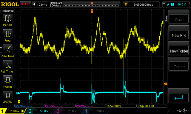
As you can see, there is approximately 600 mV of peak to peak noise. That amounts to about 4 InHg of peak to peak noise. You can study the image and read more into it as far as timing and when an intake valve is open and a cylinder is sucking etc.
Anyway, now I know. I will add some analog filtering and average the AtoD readings over an integer number of cycles of the waveform (revolutions).
Wes
I know I'm jabbering so please, if you're not interested ignore me. It's just that I find data acquisition fascinating.
I hooked up the MAP sensor for the first time to get a feel for what that looked like. I took a reading at ambient and according to the altimeter setting at the local airport the reading was 1 In. Hg. off. I'll study that more later but it appears that a single point cal is probably called for.
Edit: A fellow builder pointed out that by comparing my MAP reading with altimeter setting I had neglected to account for my elevation above sea level which is right at 1000 ft (~1 in.Hg). So it looks like my MAP reading was pretty much spot on. I feel much better now.
Most folks would guess that it's pretty turbulent in the intake manifold. I wanted to know: Just how turbulent is it? The manufacturer of the MAP sensor says it has a response time of 1 mSec. They never say exactly how that's calculated but I assume that at worst it means that a step change in pressure will move to within 63% of the final reading with in 1 mSec (one time constant). Anyway, pretty fast. The following image was taken with no analog filtering. Again, I included the P-Lead as a reference.
As you can see, there is approximately 600 mV of peak to peak noise. That amounts to about 4 InHg of peak to peak noise. You can study the image and read more into it as far as timing and when an intake valve is open and a cylinder is sucking etc.
Anyway, now I know. I will add some analog filtering and average the AtoD readings over an integer number of cycles of the waveform (revolutions).
Wes
Last edited by WesRagle on Fri Aug 20, 2021 12:57 pm, edited 1 time in total.
Wes Ragle
Onex #89
Conventional Gear
Long Tips
Hummel 2400 w/Zenith Carb
Prince P Tip 54x50
First Flight 06/23/2020
42.8 Hrs. as of 10/30/21
Onex #89
Conventional Gear
Long Tips
Hummel 2400 w/Zenith Carb
Prince P Tip 54x50
First Flight 06/23/2020
42.8 Hrs. as of 10/30/21
- WesRagle
- Posts: 844
- Joined: Fri Jan 05, 2018 12:35 pm
- Location: Weatherford, Tx
Re: The VeeCU
![]() by GraemeSmith » Wed Aug 18, 2021 9:10 pm
by GraemeSmith » Wed Aug 18, 2021 9:10 pm
I'm loving your Rigol scope!
Graeme JW Smith
-

GraemeSmith - Posts: 939
- Joined: Sat May 18, 2019 8:58 am
- Location: RI
Re: The VeeCU
![]() by WesRagle » Fri Aug 20, 2021 12:07 am
by WesRagle » Fri Aug 20, 2021 12:07 am
Hi Guys,
I'm having a lot of fun with it. It has a lot of "Nice to Have" capability I'm not using. One thing I would like to do with it is mount a knock sensor to the VW and use the FFT function of the scope. It would be cool to see if you could pick out knock, valve lash, etc in the spectrum. But, I'm going to run the current project to ground before going off on a science project.
Speaking of which, I have to gloat just a little.
I totally lose focus switching back and forth between Nust & Bolts and Bits & Bytes so I'm going to finish setting up the test bed before switching back to electronics. Obviously fuel flow is an important parameter for ECU development. From my experience the FLOSCAN transducer is much more accurate than the Gold Cube I am using in the Onex. I want a FLOSCAN. The problem is the current price at Aircraft Spruce is $366.00.
There aren't many perks to being an Engineer but one perk is being able to talk sales reps out of free samples. I had a flashback today and remembered talking a FLOSCAN rep out of a sample some 15 years ago. I rummaged through the boxes of unused airplane parts and found it!
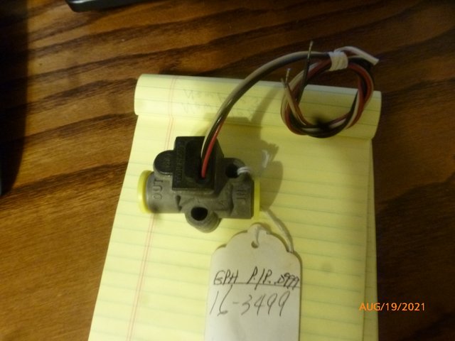
Complete with K-Factor. 3499 pulses per gallon @ 16 GPH.
SCORE!!!
Wes
GraemeSmith wrote:I'm loving your Rigol scope!
I'm having a lot of fun with it. It has a lot of "Nice to Have" capability I'm not using. One thing I would like to do with it is mount a knock sensor to the VW and use the FFT function of the scope. It would be cool to see if you could pick out knock, valve lash, etc in the spectrum. But, I'm going to run the current project to ground before going off on a science project.
Speaking of which, I have to gloat just a little.
I totally lose focus switching back and forth between Nust & Bolts and Bits & Bytes so I'm going to finish setting up the test bed before switching back to electronics. Obviously fuel flow is an important parameter for ECU development. From my experience the FLOSCAN transducer is much more accurate than the Gold Cube I am using in the Onex. I want a FLOSCAN. The problem is the current price at Aircraft Spruce is $366.00.
There aren't many perks to being an Engineer but one perk is being able to talk sales reps out of free samples. I had a flashback today and remembered talking a FLOSCAN rep out of a sample some 15 years ago. I rummaged through the boxes of unused airplane parts and found it!
Complete with K-Factor. 3499 pulses per gallon @ 16 GPH.
SCORE!!!
Wes
Wes Ragle
Onex #89
Conventional Gear
Long Tips
Hummel 2400 w/Zenith Carb
Prince P Tip 54x50
First Flight 06/23/2020
42.8 Hrs. as of 10/30/21
Onex #89
Conventional Gear
Long Tips
Hummel 2400 w/Zenith Carb
Prince P Tip 54x50
First Flight 06/23/2020
42.8 Hrs. as of 10/30/21
- WesRagle
- Posts: 844
- Joined: Fri Jan 05, 2018 12:35 pm
- Location: Weatherford, Tx
Re: The VeeCU
![]() by WesRagle » Thu Aug 26, 2021 12:52 am
by WesRagle » Thu Aug 26, 2021 12:52 am
Hi Guys,
I'm waiting parts. While waiting I decided to fool around with the fuel system some more. One thing I wanted to try was substituting a small manifold for the gascolator (surge tank) I had tried previously. I also relocated the main fuel manifold over to the firewall and moved the 40 micron fuel filter down stream of the vent. The relocation of the main fuel manifold resulted in approximately 7' of high pressure supply hose and 7' of low pressure return hose. So, much more fuel volume being circulated.
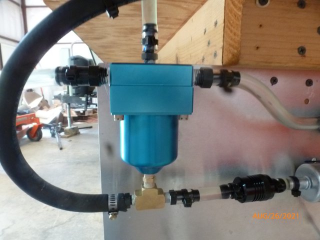
Here's what the manifold lookes like.
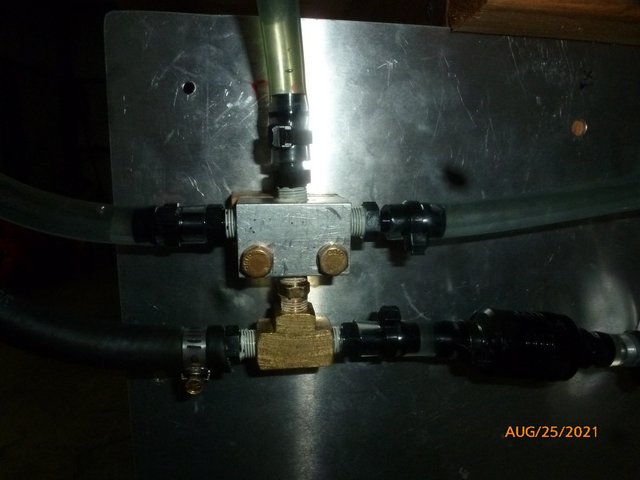
Top left is the pressure regulator return line. Top center is the vent. Top right is fuel in from the fuel tank. Bottom left is fuel to the RevFlow carb. Bottom right is fuel into the fuel pump.
When I turned the system on for the first time (dry) the vent did a decent job of eliminating air from the system. It didn't get it all the first pass but within a few circulations everything was steady state.
This test was run with Shell 93 octane. After about five minutes I took note. The fuel wasn't at all hot but the vapor forming at the fuel pressure regulator output seemed more pronounced than what I had seen with 100LL.
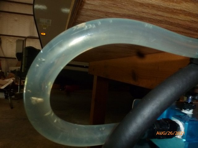
Here is what it looked like at the regulator output.
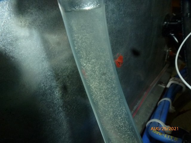
It didn't matter how long I waited, the fine bubbles just kept coming. They formed a steady parade in the return line making the 7' trip and entering the previously pictured manifold.
Again, the manifold would catch some of the bubbles but not all. I could definitely hear it and see the pressure fluctuate on the pressure gauge when a bubble slipped by.
Tomorrow it's back to the "surge tank" and I'll see how that does with auto gas.
Wes
I'm waiting parts. While waiting I decided to fool around with the fuel system some more. One thing I wanted to try was substituting a small manifold for the gascolator (surge tank) I had tried previously. I also relocated the main fuel manifold over to the firewall and moved the 40 micron fuel filter down stream of the vent. The relocation of the main fuel manifold resulted in approximately 7' of high pressure supply hose and 7' of low pressure return hose. So, much more fuel volume being circulated.
Here's what the manifold lookes like.
Top left is the pressure regulator return line. Top center is the vent. Top right is fuel in from the fuel tank. Bottom left is fuel to the RevFlow carb. Bottom right is fuel into the fuel pump.
When I turned the system on for the first time (dry) the vent did a decent job of eliminating air from the system. It didn't get it all the first pass but within a few circulations everything was steady state.
This test was run with Shell 93 octane. After about five minutes I took note. The fuel wasn't at all hot but the vapor forming at the fuel pressure regulator output seemed more pronounced than what I had seen with 100LL.
Here is what it looked like at the regulator output.
It didn't matter how long I waited, the fine bubbles just kept coming. They formed a steady parade in the return line making the 7' trip and entering the previously pictured manifold.
Again, the manifold would catch some of the bubbles but not all. I could definitely hear it and see the pressure fluctuate on the pressure gauge when a bubble slipped by.
Tomorrow it's back to the "surge tank" and I'll see how that does with auto gas.
Wes
Wes Ragle
Onex #89
Conventional Gear
Long Tips
Hummel 2400 w/Zenith Carb
Prince P Tip 54x50
First Flight 06/23/2020
42.8 Hrs. as of 10/30/21
Onex #89
Conventional Gear
Long Tips
Hummel 2400 w/Zenith Carb
Prince P Tip 54x50
First Flight 06/23/2020
42.8 Hrs. as of 10/30/21
- WesRagle
- Posts: 844
- Joined: Fri Jan 05, 2018 12:35 pm
- Location: Weatherford, Tx
Re: The VeeCU
![]() by WesRagle » Thu Aug 26, 2021 1:13 pm
by WesRagle » Thu Aug 26, 2021 1:13 pm
HI Guys,
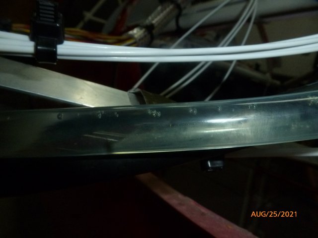
OK, I took the screen back out of the gascolator and replaced the small manifold with the gascolator. Again, fuel inputs and vent on the top and fuel outlets on the bottom.
This is the same thing as the small manifold I tried except the diameter of the path from fuel input to output is much larger so the vapor can't get caught up in the flow. Problem solved, no vapor at the fuel pump input so no fluctuation in pressure.
Pic of the vapor making its way around the last turn and into the gascolator.
Things I think I learned:
1) Fuel pressure regulators make vapor at the outlet.
EDIT: I just walked out and turned the pump on again. There was a delay before the vapor appeared at the regulator output and then it appeared suddenly. So ..., it might be that the pump itself is generating the vapor. Wish I could see through high pressure hose :-)
2) The vapor is not in a hurry to condense back into the surrounding fuel.
3) Fuel pumps don't like vapor at their input. Vapor causes the pump speed to surge and the pressure to fluctuate.
In my opinion the vapor in the lines needs to be eliminated. It may be that the easiest way to eliminate the vapor is to stay on the beaten path and return fuel to the fuel tank. I'll have plenty of time to think about that but for now I'll just leave it alone and press on.
BTW, I did finally get two pipe extensions I could use.
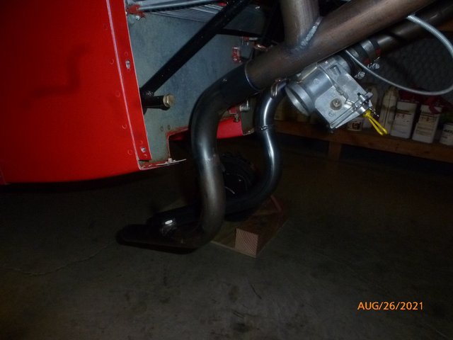
Wes
OK, I took the screen back out of the gascolator and replaced the small manifold with the gascolator. Again, fuel inputs and vent on the top and fuel outlets on the bottom.
This is the same thing as the small manifold I tried except the diameter of the path from fuel input to output is much larger so the vapor can't get caught up in the flow. Problem solved, no vapor at the fuel pump input so no fluctuation in pressure.
Pic of the vapor making its way around the last turn and into the gascolator.
Things I think I learned:
1) Fuel pressure regulators make vapor at the outlet.
EDIT: I just walked out and turned the pump on again. There was a delay before the vapor appeared at the regulator output and then it appeared suddenly. So ..., it might be that the pump itself is generating the vapor. Wish I could see through high pressure hose :-)
2) The vapor is not in a hurry to condense back into the surrounding fuel.
3) Fuel pumps don't like vapor at their input. Vapor causes the pump speed to surge and the pressure to fluctuate.
In my opinion the vapor in the lines needs to be eliminated. It may be that the easiest way to eliminate the vapor is to stay on the beaten path and return fuel to the fuel tank. I'll have plenty of time to think about that but for now I'll just leave it alone and press on.
BTW, I did finally get two pipe extensions I could use.
Wes
Wes Ragle
Onex #89
Conventional Gear
Long Tips
Hummel 2400 w/Zenith Carb
Prince P Tip 54x50
First Flight 06/23/2020
42.8 Hrs. as of 10/30/21
Onex #89
Conventional Gear
Long Tips
Hummel 2400 w/Zenith Carb
Prince P Tip 54x50
First Flight 06/23/2020
42.8 Hrs. as of 10/30/21
- WesRagle
- Posts: 844
- Joined: Fri Jan 05, 2018 12:35 pm
- Location: Weatherford, Tx
Re: The VeeCU
![]() by WesRagle » Fri Oct 29, 2021 1:34 pm
by WesRagle » Fri Oct 29, 2021 1:34 pm
HI Guys,
This time of year is perfect around Tx. for camping in the state parks. So ..., I've been totally distracted.
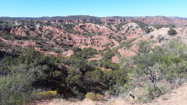
Just back from Caprock Canyons State Park.
One problem with park camping is: What to do after you have walked all you want to (and all the beer is gone)? A friend had an eBike along on this trip and I'm hooked. These things are great. The only problem is finding a good Old Man Bike that will actually haul you out of a canyon on the multi-use trails. Since the inexpensive hub drive bikes aren't up to the task I'm going to try and build an inexpensive 1000 Watt mid-drive bike. I hope to build one like that shown in this video with different bars and a smaller front sprocket to help with hill climbing. I know nothing about bikes so a bit of a learning curve involved. Parts on order. Another distraction.
https://www.youtube.com/watch?v=Qg5Z9csJZl8
OK, back to the VeeCU.
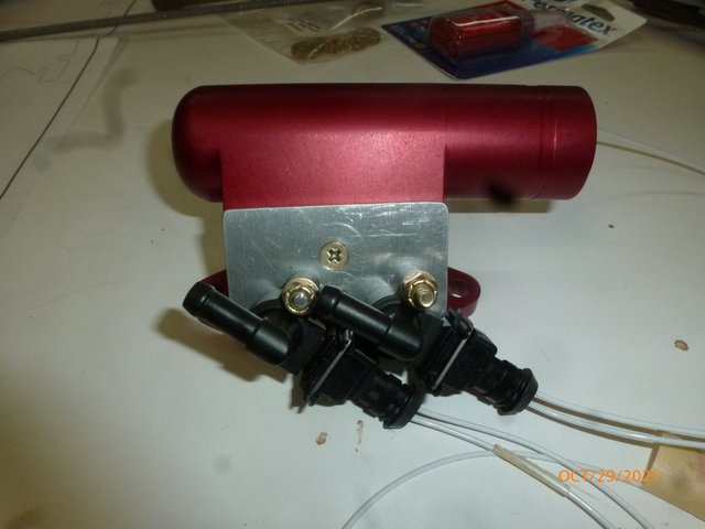
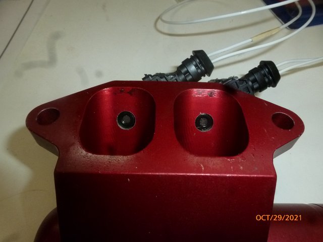
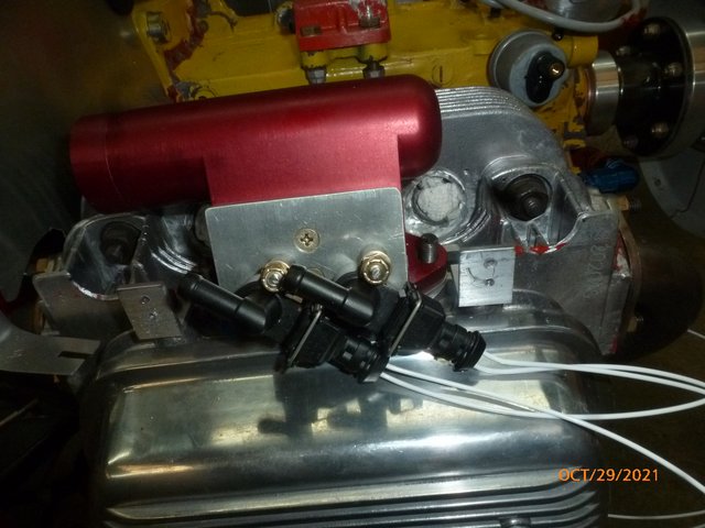
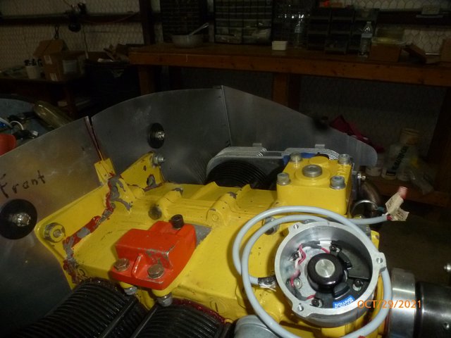
I attached the injectors I chose to the red logs. I don't consider the install airworthy but it will keep the VeeCU project moving along. You have to mount the injectors a low as possible in the "Red Log" to get a straight shot down the intake. Installing the Red Log on this conversion requires a spacer to clear the plugs.

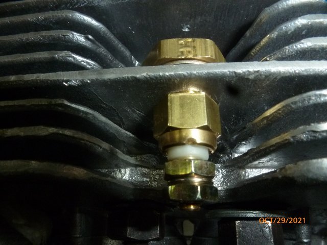
I found an inexpensive CHT sensor to enable warm up and cranking enrichment. I tapped a 1/8" NPT hole in the fin. I'll screw the sensor in and secure it with an NPT nut and high temp lock tight.
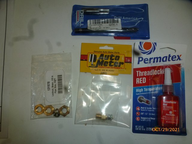
Data from 100 Deg F upward is available here:https://www.autometer.com/sensor_specs I generated the curve from 32 Deg F to 100 Deg F by placing a thermometer and the sensor in an ice bath and taking data as the water warmed up after the ice melted. I also got one more data point a -7 Deg. F by placing the thermometer and sensor in the freezer. That will be "good enough" for its intended purpose.
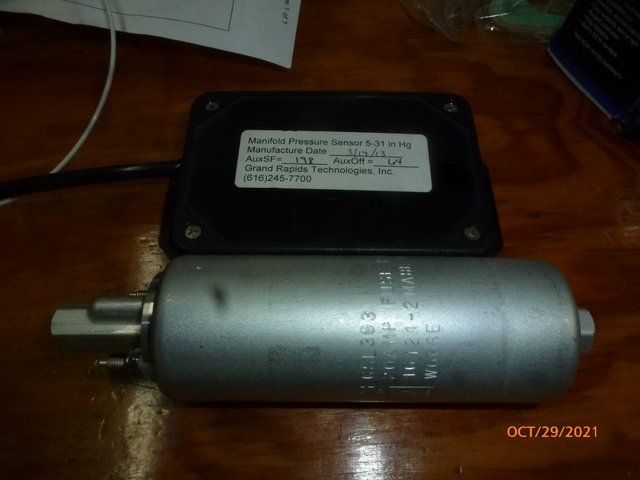
I have a Walbro fuel pump I'll be testing. I also have a MAP sensor for the EIS to help verify the accuracy of my calculations.
I'm currently working on a cooling shroud to extend run time without over-heating.
The long vernier control cables finally came in last week. Now I can route everything over to the work bench.
I truly wish one of you mechanically minded folks would consider taking on the task of designing a generic EFI intake that would bolt right on to the VW heads.
Wes
This time of year is perfect around Tx. for camping in the state parks. So ..., I've been totally distracted.
Just back from Caprock Canyons State Park.
One problem with park camping is: What to do after you have walked all you want to (and all the beer is gone)? A friend had an eBike along on this trip and I'm hooked. These things are great. The only problem is finding a good Old Man Bike that will actually haul you out of a canyon on the multi-use trails. Since the inexpensive hub drive bikes aren't up to the task I'm going to try and build an inexpensive 1000 Watt mid-drive bike. I hope to build one like that shown in this video with different bars and a smaller front sprocket to help with hill climbing. I know nothing about bikes so a bit of a learning curve involved. Parts on order. Another distraction.
https://www.youtube.com/watch?v=Qg5Z9csJZl8
OK, back to the VeeCU.
I attached the injectors I chose to the red logs. I don't consider the install airworthy but it will keep the VeeCU project moving along. You have to mount the injectors a low as possible in the "Red Log" to get a straight shot down the intake. Installing the Red Log on this conversion requires a spacer to clear the plugs.
I found an inexpensive CHT sensor to enable warm up and cranking enrichment. I tapped a 1/8" NPT hole in the fin. I'll screw the sensor in and secure it with an NPT nut and high temp lock tight.
Data from 100 Deg F upward is available here:https://www.autometer.com/sensor_specs I generated the curve from 32 Deg F to 100 Deg F by placing a thermometer and the sensor in an ice bath and taking data as the water warmed up after the ice melted. I also got one more data point a -7 Deg. F by placing the thermometer and sensor in the freezer. That will be "good enough" for its intended purpose.
I have a Walbro fuel pump I'll be testing. I also have a MAP sensor for the EIS to help verify the accuracy of my calculations.
I'm currently working on a cooling shroud to extend run time without over-heating.
The long vernier control cables finally came in last week. Now I can route everything over to the work bench.
I truly wish one of you mechanically minded folks would consider taking on the task of designing a generic EFI intake that would bolt right on to the VW heads.
Wes
Wes Ragle
Onex #89
Conventional Gear
Long Tips
Hummel 2400 w/Zenith Carb
Prince P Tip 54x50
First Flight 06/23/2020
42.8 Hrs. as of 10/30/21
Onex #89
Conventional Gear
Long Tips
Hummel 2400 w/Zenith Carb
Prince P Tip 54x50
First Flight 06/23/2020
42.8 Hrs. as of 10/30/21
- WesRagle
- Posts: 844
- Joined: Fri Jan 05, 2018 12:35 pm
- Location: Weatherford, Tx
Re: The VeeCU
![]() by GraemeSmith » Sat Oct 30, 2021 5:23 am
by GraemeSmith » Sat Oct 30, 2021 5:23 am
How are you going to handle getting (outside preferred?) filtered air into the "red log" manifolds?
Graeme JW Smith
-
GraemeSmith - Posts: 939
- Joined: Sat May 18, 2019 8:58 am
- Location: RI
Re: The VeeCU
![]() by WesRagle » Sat Oct 30, 2021 1:28 pm
by WesRagle » Sat Oct 30, 2021 1:28 pm
Hi Graeme,
The general idea is to simply modify the intake logs and leave the rest of the induction system in tact. The ideal throttle body would be an AeroInjector but I intend to use what was supplied with the plane, a RevFlow.
The builder of the test bed simply took intake air from beneath the cowl with no filter. I'll do the same for the "Proof of Concept". If the experiment makes it to "Prototype" and is installed on my Onex I'll use the filtered cold air induction I have. The problem I'll have with the Onex is switching from the Zenith to an AeroInjector so as to provide idle cutoff while running on EFI.
Wes
Wes Ragle
Onex #89
Conventional Gear
Long Tips
Hummel 2400 w/Zenith Carb
Prince P Tip 54x50
First Flight 06/23/2020
42.8 Hrs. as of 10/30/21
Onex #89
Conventional Gear
Long Tips
Hummel 2400 w/Zenith Carb
Prince P Tip 54x50
First Flight 06/23/2020
42.8 Hrs. as of 10/30/21
- WesRagle
- Posts: 844
- Joined: Fri Jan 05, 2018 12:35 pm
- Location: Weatherford, Tx
Re: The VeeCU
![]() by WesRagle » Sat Nov 06, 2021 3:55 pm
by WesRagle » Sat Nov 06, 2021 3:55 pm
HI Guys,
OK, I'm just about finished with the cooling shroud.
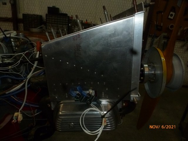
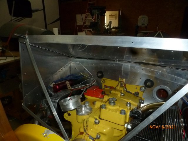
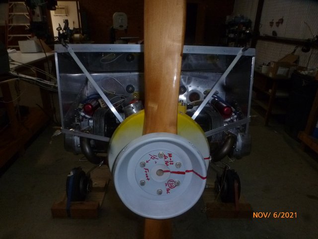
It started life as a Sonex baffle kit. I didn't use much of the kit but it did get me started. Mostly made from leftovers, scrap, and Home Depot aluminum. I think it's plenty stout.
I need to secure the wiring and add some fasteners and then I can move on to making sure all the sensors are working properly.
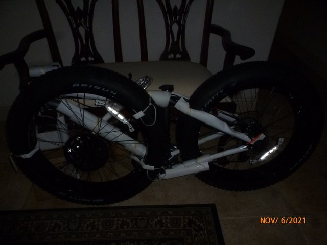
Now for a break. Santa Clause came early so I need to get the Fat Tire assembled, take some measurements, and get the parts on order for the electrification.
Wes
P.S. I forgot to turn the flash off on the camera so the pics look pretty bad. Sorry.
OK, I'm just about finished with the cooling shroud.
It started life as a Sonex baffle kit. I didn't use much of the kit but it did get me started. Mostly made from leftovers, scrap, and Home Depot aluminum. I think it's plenty stout.
I need to secure the wiring and add some fasteners and then I can move on to making sure all the sensors are working properly.
Now for a break. Santa Clause came early so I need to get the Fat Tire assembled, take some measurements, and get the parts on order for the electrification.
Wes
P.S. I forgot to turn the flash off on the camera so the pics look pretty bad. Sorry.
Wes Ragle
Onex #89
Conventional Gear
Long Tips
Hummel 2400 w/Zenith Carb
Prince P Tip 54x50
First Flight 06/23/2020
42.8 Hrs. as of 10/30/21
Onex #89
Conventional Gear
Long Tips
Hummel 2400 w/Zenith Carb
Prince P Tip 54x50
First Flight 06/23/2020
42.8 Hrs. as of 10/30/21
- WesRagle
- Posts: 844
- Joined: Fri Jan 05, 2018 12:35 pm
- Location: Weatherford, Tx
Who is online
Users browsing this forum: No registered users and 3 guests